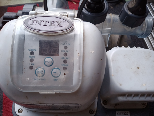
Permanent $1 fix
of ERROR 91 LOW SALT and ERROR 92 HIGH SALT
This article is
about fixing SALT LEVEL ERROR, while keeping all other function of saltwater
system working, like automatic changing of polarity to keep electrocatalytic
cell clean, timing and copper dispensing. I assume you came here, because you
already cleaned the cell by vinegar and your salt level in pool is correct, but
you still getting LOW SALT ERROR.
So, please make
sure you are not fixing dirty cell or wrong salt level. First, keep your cell clear
and your salt level at 3000-3500ppm.
This is how clean
cell looks like. If you have this and your salt level is correct, then continue
to fix.
You can read on
internet about few fixes. I have tried all, none of them worked permanently or
kept the system fully working. First two solutions suggested to connect copper
electrode parallel to the cell or reverse polarity. I have tested both, and it
worked. But just day or two and then bam, LOW SALT ERROR again.
So another
solution was to connect the cell directly to the power. Well, this has several
side effects. It did not solve the error, it just keep cell runing. So if you
turn the unit on, you will still get annoying beeping sound and if you turn it off, cooling
fan will not run. And - the most important - even when unit is on, the polarity changing will not work,
timing will not work and copper dispensing will not work. So, this was my last
option, if everything fails. Furtunately I do not need it anymore.
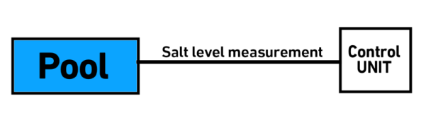
I was thinking,
how it works. It actually measures the salt level by measuring water
resistance. The current going through water is generating voltage on shunt and
this is measured. Like this:
So the idea is to
stop measuring actual level of salt and use fake level instead, set by user.
Like this:
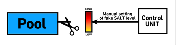
This would wipe
out the ERROR 91 and ERROR 92 once and forever. And... it actually WORKS!
It took me few
days searching and trying internet hints and finally finding my own, so here is
the time to consider buying me a beer, because you will fix this issue forever!
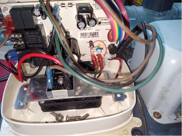
Disconnect the
unit from power grid and pool hoses. Do not forgot to CLOSE your filtration unit and pool jets, just to make sure water will not come out. Open
the cover by unscrewing four screws. Take photo how to connect all wires back or
mark them by numbers. Disconnect all wires and remove the board.
<
Locate
JP1 wire connection. This is the measurement line. Cut it on the left side.
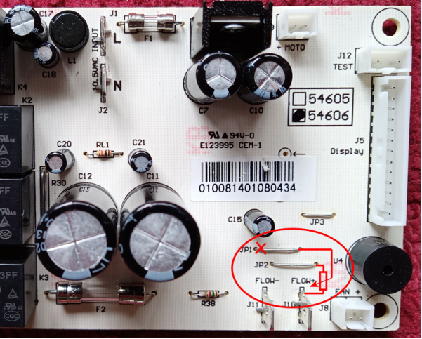
The idea is to put little
adjustable resistor here, which will fake the salt level we need.
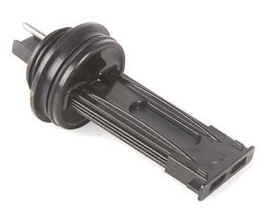
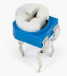
Buy 100K ohm adjustable
resistor like this:
 or
or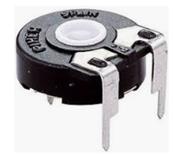
See the image
bellow, how it works. We will use the wiper to set the fake level. We will
connect low level to left leg and high level to right leg.
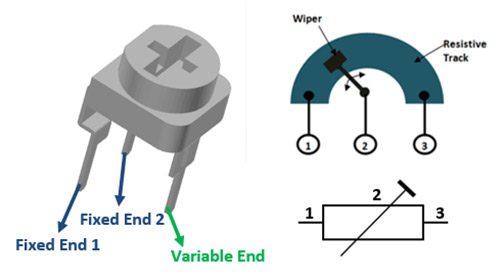
You have to
connect the variable end (the leg in middle or the one in the opposite to two
legs) to the right side of JP1. Connect right end to JP2 and left end to FLOW+
terminal.
Just like this:
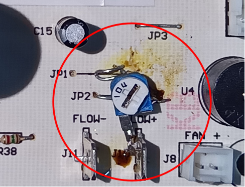
Set the
adjustable top by screwdriver to 1/3 path or 45°. Like on photo. If you set it
too much on left, you will get ERROR 91 LOW SALT. If you set it too much on
right, you will get ERROR 92 HIGH SALT. This position worked in my case, but if
you will get ERROR, just move it a bit in correct direction.
Put all wires
back withou any change. See little blue adjustable FAKE SALT LEVEL unit
installed ;-)
Close the cover,
connect it back to pool hoses and simply run it. All functions remains the same
and you will never get LOW or HIGH salt error again. Simply errors 91 and 92 are
gone forever.
Keep in mind,
that you set the salt level manually, that mean the unit is not measuring it.
So you have to do it yourself periodically! The unit will never warn you! Also,
you have to check the cell. There is no automatic control anymore.
I am very happy
with this fix. Buy me a beer and enjoy error free salt water system :-)
Is your circuit board different? Well, the basic
idea is to trace line from shunt to control unit. Shunt is U shaped thick wire on the board. Trace the line.
It will probably lead to 8 pin integrated circuit, might be labeled as UC358. Output from this circuit will
go to the main processing unit. You need to cut this trace and connect resistor between + and GND and the wiper to the
processing unit.